
GZG10 DC Operating Power System
GZG10 supplies DC power for switchgear operation, protection and control circuits in substations, power plants and industrial distribution facilities. AC input, rectifier modules, batteries, DC distribution and monitoring are configured to suit the load and backup requirements.
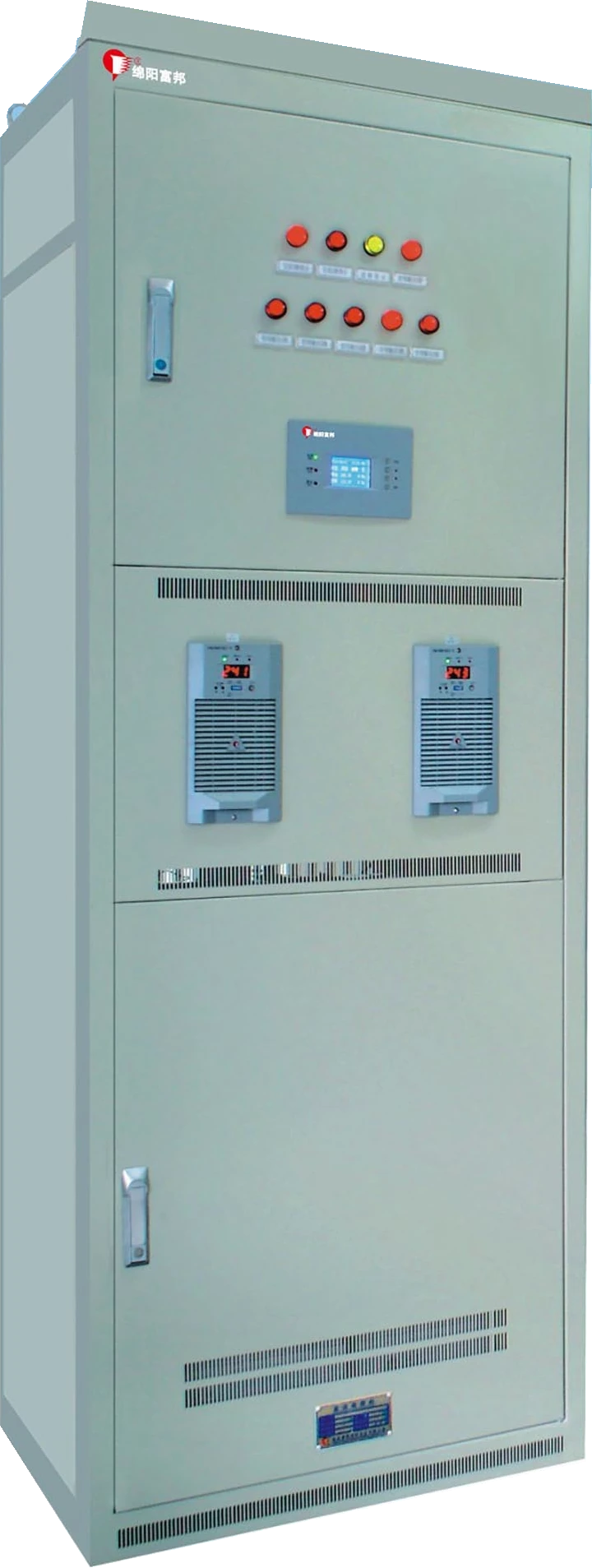
System Architecture
Rectifier modules convert incoming AC to DC, supplying the loads and charging the battery. If the AC supply is lost, the battery supplies the connected DC circuits. Outgoing feeders are selected for the load groups, circuit count and protection requirements.
Redundancy, Maintenance & Monitoring
The system can use a single or dual AC input, with automatic changeover available for a dual supply. Parallel rectifier modules support N+1 or N+M redundancy and hot-swap maintenance. The module arrangement must provide the required load and charging capacity under the specified operating conditions.
Monitoring & Battery Care
Battery management includes charging control and temperature compensation. Battery inspection, insulation monitoring and feeder status monitoring can be included in the configuration. Battery capacity and backup duration are selected against the load profile, end-of-discharge voltage and site conditions.
Interfaces & Communication
Physical interfaces: The catalogues list RS232, RS485 and RS422. Confirm the physical interface on the selected monitoring unit.
Protocols: The catalogues list IEC 101, IEC 103, Modbus, DNP3.0 and CDT91 for controller selection. The supplied monitoring version and protocol must be agreed for the connection to your supervisory system.
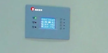
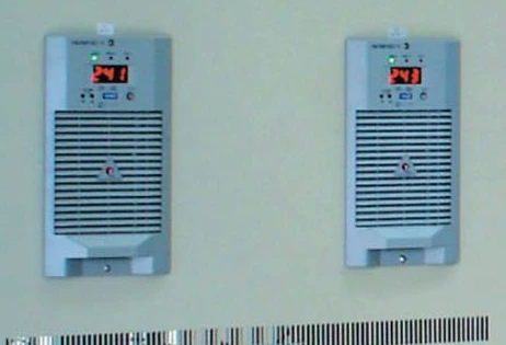
Cabinet controls & modules
The cabinet views below show the monitoring panel and rectifier-module fronts. Controller type and module arrangement are selected for the required system.
Parameters & Configuration
To configure the system, start with the following details where known. You can enquire while requirements are still being defined.
- AC input: available supply and single or dual input.
- DC operating load: required DC voltage, load current and outgoing circuits.
- Backup requirement: backup time, battery arrangement and site conditions.
- Monitoring / interfaces: required functions and the system to be connected.
Series selection information
| Item | Selection condition |
|---|---|
| AC input | 380 or 220 VAC, ±15% |
| DC output options | 110 or 220 VDC; these are the options shown here, not the full series range |
| Rectifier module count | Up to 24, selected for load and charging current |
| Battery capacity | Up to 3,000 Ah, selected for system voltage and backup requirements |
| Environment | −10 to 40°C; relative humidity ≤90% |
| Cooling | Natural cooling or controlled fan cooling, depending on configuration |
Module count and battery capacity are selection limits. Available combinations depend on the required DC voltage, load and charging duty. Share these requirements to confirm the appropriate module and battery arrangement.
Configuration choices
- Single or dual AC input and the required redundancy arrangement.
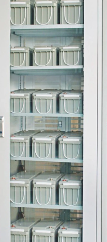
- Battery accommodation, capacity and backup requirements.
- Outgoing feeders, monitoring functions and the selected controller interface.
Battery supply, capacity and cabinet arrangement form part of the agreed quotation scope.
One specific configuration example
The following 200 Ah configuration is a single example, rather than the default for the series.
| Item | Configuration example |
|---|---|
| Model | GZG10-200Ah/220V/40A-M |
| AC input | 380 VAC |
| DC output | 220 VDC, 40 A |
| Battery capacity designation | 200 Ah |
Select system voltage, rectifier current, batteries and outgoing circuits for the project. Request technical documents for the configuration you need.
Frequently Asked Questions
Which details determine the DC system configuration?
Start with the required DC voltage, operating load current and backup duty. Add the available AC input, outgoing circuits and site conditions. Rectifier modules and batteries are selected together for these requirements.
Do I need a complete specification to enquire?
No. Start with the application and any known voltage, load or existing-equipment details. Battery, module and feeder requirements can then be reviewed.
Are batteries included in the quotation?
Battery supply is confirmed as part of the agreed project scope. Capacity and cabinet arrangement are specified in the quotation; the illustrated examples do not define a default package.
Can any rectifier module be removed while the system is running?
Hot-swap maintenance must follow the equipment operating instructions, with sufficient capacity remaining for the running load. The redundancy arrangement is selected as part of the system design.
Can GZG10 connect to our monitoring system?
Monitoring can be configured for the required interface and protocol. Share the existing system's communication requirements so the connection can be checked.
Configuration & Technical Documents
Agree the DC system scope
- Supply & charging
- Confirm the AC input arrangement, selected DC voltage, rectifier modules and redundancy requirement.
- Battery & outgoing circuits
- Identify battery capacity and autonomy needs, battery accommodation, and the feeder schedule. Confirm whether batteries are included in the quotation.
- Monitoring & interfaces
- Specify signals and communication requirements for the selected monitoring version. Optional conversion or voltage-reduction functions require a defined configuration.
Published selection limits are not a ready-made bill of materials. The 200 Ah / 220 V / 40 A configuration shown above is one example.
Technical information for your purchase
Available on this page: catalogue selection information, construction or system relationships, and configuration limits.
Request for your configuration: the relevant catalogue, drawings and supporting technical documents. Drawing availability and any report’s applicable model and scope need review; they are not universal product certifications.
Send the details you have. A complete specification is not required to start; unresolved selections can be discussed before the supply scope is agreed.