
Integrated AC/DC Station Power System
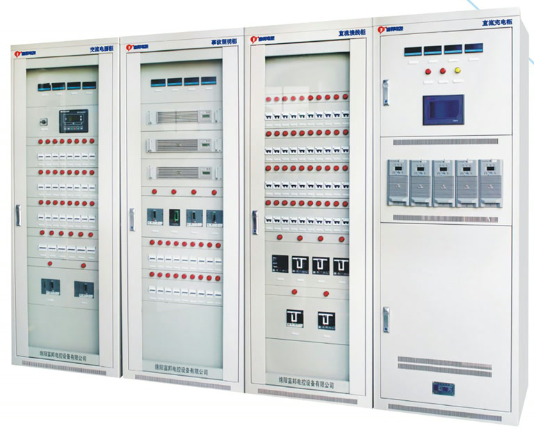
Manage station AC, DC, UPS/inverter and telecom power through one monitoring system. The equipment combines the required power supplies for auxiliary loads in digital, intelligent and other substations that need centralised monitoring.
System Functions
Station AC
Input changeover
AC distributionDC power
Rectifiers & battery
Operating & control circuitsUPS / inverter
AC supply function
Specified AC loadsTelecom
DC/DC modules
Telecom DC loadsArrows show each power function. Dashed connections represent monitoring, not a series power path. Final wiring follows the project drawings.
The AC section provides input changeover, distribution and status monitoring. Rectifier modules, batteries and DC feeders supply operating and control circuits. The UPS/inverter section serves the specified AC loads, while DC/DC modules supply telecom loads.
The architecture can use a common DC battery for the associated subsystems. Battery voltage and capacity, isolation and protection, subsystem compatibility and fault boundaries are defined in the technical proposal.
Module Selection & Configuration
| Section | Selection parameters |
|---|---|
| AC input | 380 VAC ±15% |
| DC system | 220 or 110 VDC |
| Rectifier modules | 5, 10, 20 or 40 A per module; up to 24 modules |
| UPS/inverter modules | 1–10 kVA per module; up to 8 modules |
| Telecom DC/DC | 48 or 24 VDC output; 10, 20, 25 or 30 A modules; up to 8 modules |
| Battery capacity | Up to 3,000 Ah, subject to the system configuration |
| Environment | −10 to 40°C; relative humidity ≤90% |
These are component selection limits. They do not define a single system rating or permit every combination. Total capacity, parallel operation, backup arrangements and protection coordination are selected for the loads and operating requirements.
Monitoring & System Selection
The monitoring system collects electrical measurements, operating states and alarms from the subsystems. AC input changeover can use contactors or an ATS, with control modes selected for the project. Ethernet and IEC 61850 communication are available for supervisory integration; the connection and point list are agreed in the technical proposal.
Integrated or separate power supplies?
Consider an integrated system when several station power supplies need common monitoring. For DC operating power alone, start with GZG10. Where telecom or UPS loads have separate requirements, establish their voltage, load and backup arrangements before choosing how to combine the systems.
Configuration & Technical Documents
Known AC and DC loads or an existing single-line diagram help define power supplies, feeders, monitoring and batteries.
Start with the application, equipment type or a single-line diagram. Share the details you have; a complete specification is not required for an initial enquiry.
Request available product documentation, drawings and technical information for your configuration.