
Wall-mounted DC Power System
Operating and control power for small switching stations, substations and user distribution systems. The wall-mounted assembly brings rectifiers, monitoring, distribution and batteries into one compact installation.
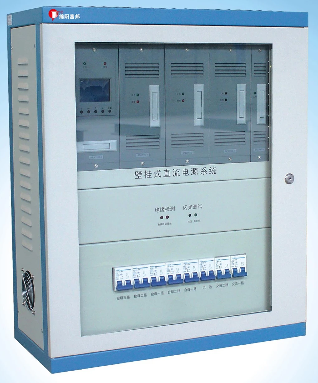
A Compact Operating-power Installation
Use the system for switchgear operation, relay protection and automatic-control circuits where a floor-standing DC cabinet is not the preferred arrangement. Confirm the mounting surface, access and battery arrangement with the installation drawing.
| Installation item | Arrangement |
|---|---|
| Assembly | Wall-mounted enclosure integrating rectification, monitoring, DC distribution and battery. |
| Cable entry | Bottom entry and exit; four Ø30 mm openings are listed. |
| Environment | −10 to 40°C; relative humidity ≤90%. |
AC / PT Supply & DC Output
| Selection item | Options / condition |
|---|---|
| Normal AC source | 220 VAC ±15% |
| PT input option | 100 VAC ±10% |
| DC system voltage | 220 or 110 VDC |
| Rectifier arrangement | Up to three modules; module version and current rating selected for the system. |
| PT-fed output limit | 220 V system: 2 A; 110 V system: 3 A. These are PT-mode limits, not normal rectifier ratings. |
PT capacity and protection must be checked against the intended duty. Specify continuous control demand separately from the short operating pulse of the switching mechanism.
Battery, Protection & Monitoring
Battery management monitors charging/discharging status. The monitoring unit can connect to an 18-cell voltage inspection unit and provides earth-insulation alarms. Rectifier modules are hot-swappable; a maintenance bypass arrangement is described for the monitoring circuit.
RS232 / RS485 interfaces and CDT / Modbus protocol options are listed. Confirm the selected monitor and the required remote signals.
Battery capacity, battery layout and module version are confirmed together in the configuration proposal. They are not interchangeable across enclosure versions.
Selection Questions
What information is needed for wall mounting?
Share the available wall space, mounting constraints, cable approach and maintenance access. A project drawing confirms the enclosure and battery arrangement.
Can the PT input supply the normal full output?
The PT-fed mode has its own current limit: 2 A for the 220 V system or 3 A for the 110 V system. Check the load duty and PT source before selecting it.
Discuss Your Configuration
Share the information you have. A complete specification is not required for an initial enquiry.
- 110 or 220 VDC and continuous control load.
- Operating pulse, battery autonomy and available AC/PT source.
- Wall space, cable route and monitoring requirements.
Ask for the available catalogue, drawings and technical documents for your equipment.